Passive Components:
Those components which do not need any power to operate or run are called passive components. There are many variations in passive components which include Resistance, Inductance, Capacitance, Kirchoff's law, linearity, and more. These are the basic components that are required for the basic electronic circuit and certain theory. These components are mostly used in the electronic field and in others as well. We can buy it simply in the market at a cheap price with better quality. Each of the components has its own sign in electronic language. Some of the passive components are described below with their circuit diagram, sign, and formula:
1. Resistance
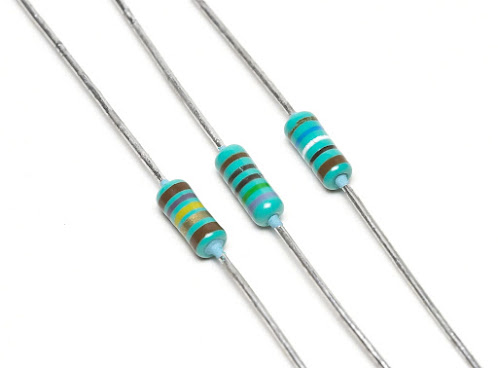
It is the property a substance that opposes the flow of current through it. The resistance of a material is given by
R=ρ✕l/A
ρ= resistivity or coefficient of resistance of the material,
l= length of the material,
A= area of cross-section of the material.
According to ohm's law,
R=V/I
Where
V= voltage applied or potential difference across the resistor,
I= current through a resistor.
Its SI unit is ohm or Ω.
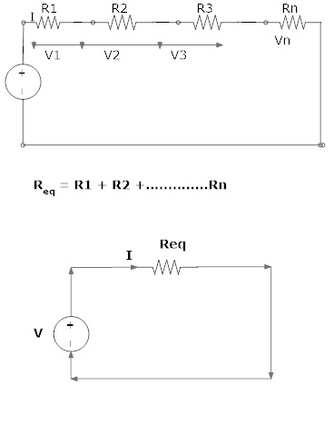
Series combination of resister:
Where Req = equivalent resistance of the circuit
2. Inductance
It is the property of a substance which can store the charge by virtue of magnetic flux coupling in changing current across it.
In terms of changing current, inductance (L) is given by
L=(V/di/dt)
where
i= current through the inductor,
v= voltage applied.
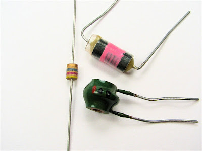
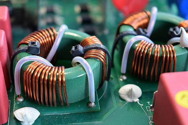
Figures below show the clear vision of inductor:
Its unit is Hor Henry.
Application
- used as DC smoothing purpose in power supply
- in running the frequency channel in the receiver
- in oscillator to generate frequency
- used as a filter.
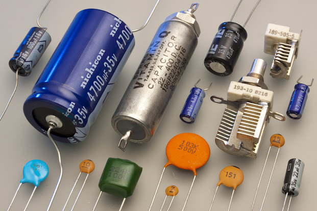
3. Capacitance
the property of trending to oppose the change in voltage or storing the charge is called capacitance. It is denoted by C and given by
C=q/v
where
q= charge stored in the capacitor
v= voltage applied.
Series combination
(1/Ceq) = (1/C1) + (1/C2) + ...
Parallel combination:
Ceq = C1 + C2 + .......
Where, Ceq = equivalent capacitance
Its unit is Fared or F.
Application of capacitors:
- used for filters
- signal shaping circuits
- used in tuning, oscillating, etc.
- voltage dividing application
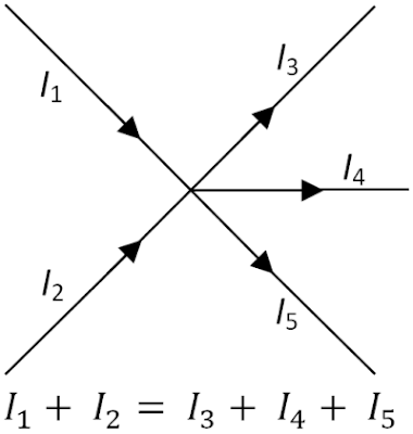
The first law (Point or current law):
"The sum of the currents entering a junction is equal to the sum of currents leaving the junction."
ΣCurrent entering = Σ current leaving
For the circuit we have ⟶
This law is also known as the law of conservation of charge.
The second law (Mesh or voltage law):
"The sum of e.m.faround any closed loop of a circuit equals the sum of the potential drop in that loop."
Σ E - Σ IR drops = 0 i.e Σ potential drop.
This law is also known as the law of conservation of energy.
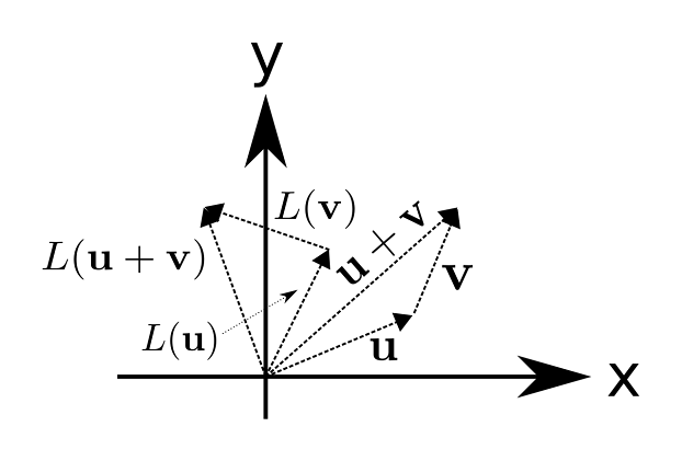
5. Linearity:
A system is said to be linear if the output is linearly proportional to the input. Most of the system requires linearity because the conversion from a scale reading to the corresponding measured value of input quantity is most convenient if one merely has to be multiplying by a fixed constant rather than calibration curve or compute a non-linear calibration equation.
Signal Sources:
In any electric and electronic circuit, there should be a source either voltage or current source.
Voltage source:
Any source which produces voltage output continuously is known as a voltage source. the voltage source may be an AC or DC source.
ii. An ideal voltage source:
It is a source that maintains a constant terminal voltage regardless of the value of current drawn from it.
ii. A practical voltage source:
It is a source in which the voltage across the terminal of the source keeps falling the current through it increases.
Current source:
It is a source that delivers energy through its terminals.
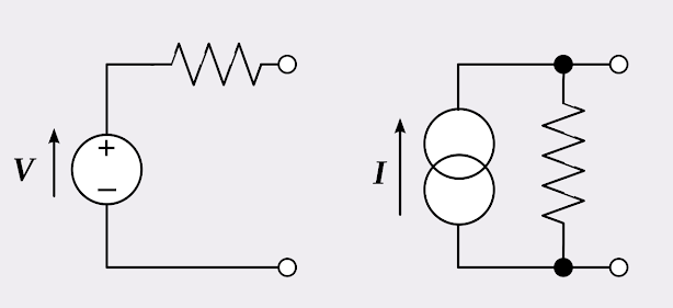
Below ideal and practical source are given:
Controlled source or dependent sources
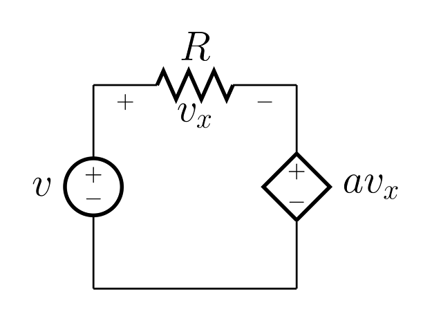
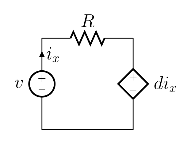
A dependent on a voltage source or a current source whose value depends on a voltage or current somewhere else in the network. The voltage or current values will be proportional to some other voltage or current in the circuit. they are given below:
Voltage-controlled current sources
In case the control variable is voltage and the output of the source is current, it is VCCS. This is a transconductance amplifier.
e.g. JFET, MOSFET
Current controlled current source
the current dependent current source (CCCS) is as shown in fig.
e.g BJT
Voltage-controlled voltage source
The voltage-dependent voltage source (VCVS).
e.g Transformer
Current controlled voltage source
the current dependent voltage source (CCVS).
Concept of Gain
Gain is defined as the ratio of the output quantity to the input quantity.
Quantity may be voltage, current, or power.
Transconductance
Transconductance, also known as mutual conductance, is a property of certain electronic components. Conductance is the reciprocal of resistance. Transconductance, meanwhile, is the ratio of the current change at the output port to the voltage change at the input port. It is written as gm . For direct current, transconductance is defined as follows:
gm = ΔIout/ΔVin
For small-signal alternating current, the definition is simpler:
gm = iout/vin
Transconductance is an expression of the performance of a bipolar transistor or field-effect transistor (FET). In general, the larger the transconductance figure for a device, the greater the gain(amplification) it is capable of delivering, when all other factors are held constant. Formally, for a bipolar device, transconductance is defined as the ratio of the change in collector current to the change in base voltage over a defined, arbitrarily small interval on the collector- current versus base-voltage curve.
Transimpendance
Transimpedence, infrequently referred to as mutual resistance of trans resistance, is the reciprocal of transconductance. It is a contraction of ''transfer resistance''. It refers to the ratio between a change of the voltage at two output points and related change of current through two input points and is notated as rm. The SI unit for trans resistance and trans-impedance is simply the ohm.
___________________________________________________________________________________
If you have any doubt then mention in the comment, please.
👇👇👇👇👇👇👇👇👇👇👇👇👇👇👇👇👇👇👇👇👇👇👇👇👇👇
